Case Study
Greg Greenberg DDS
Dr. Greenberg began practicing orthodontics in 1988 and has spent his entire career caring for two generations of families in the Frisco and North Dallas metropolitan areas. He is a member of the American Association of Orthodontists, Greater Dallas Association of Orthodontists and Southwest Association of Orthodontists, along with many other dental associations. He received his certificate in orthodontics from Columbia University School of Dental and Oral Surgery, a Doctor of Dental Surgery (DDS) from Baylor College of Dentistry and his Bachelor of Science from Tulane University. He is a native of Dallas and married his college sweetheart, Lauri. They have two lovely children, Rachel and Mitchell. In his free time, he enjoys fishing and playing tennis. Dr. Greenberg and his team have received numerous prestigious consumer and peer nominated awards for their excellent patient experience.

Case Overview
Supernumerary teeth are considered one of the most common dental anomalies during the primary and early mixed dentition stages1. Supernumerary teeth may erupt in any part of the dental arch, but they most commonly occur in the maxillary midline region, i.e. Mesiodens, which account for approximately 80% of all supernumerary teeth2. When the patient highlighted in this clinical case initially presented, the office did not have 3D imaging, and therefore the initial records included only a 2D panoramic and cephalometric images. Panoramic images are often difficult to interpret due to significant superimposition; additionally, structures that are not centered in the focal trough are often not visualized or obscured beyond recognition. Although the mesiodens can be visualized on the panoramic with 20/20 hindsight, it is difficult to see and was initially overlooked on the 2D panoramic image (Figure 2). Additionally, even on the best panoramic, the exact location of the mesiodens cannot be determined.
Findings
An 8-year-old female presented to the office for orthodontic treatment. She was relatively small for her age. The preliminary orthodontic records included intra- and extraoral photographs (Figure 1), a 2D digital panoramic (Figure 2) and a 2D digital cephalometric radiograph (Figure 3). The panoramic image depicts age appropriate mixed dentition. She had a Class I molar relationship and is mild division 2. Severe crowding was noted in both the maxilla and mandible. The patient also had upper and lower arch length discrepancy. Clinical evaluation revealed a straight profile.
Initial (Phase I) Treatment Plan
Phase I treatment included a palatal expander and 2x4s appliances (brackets on all incisors and first molars); open coil springs were employed in both the maxilla and mandible. The palatal expander and 2x4s were removed after 22 months and an Essix Retainer (night-time use only) was used for retention. The patient was put on a 6-month recall for observation of growth.
Figure 1. Initial Orthodontic Photos
Figure 2. 2D digital panoramic radiograph from initial consultation for orthodontic evaluation
Figure 3. 2D digital cephalometric radiograph from initial consultation
3D Imaging (i-CAT FLX) is Introduced to the Office
After years of carefully researching 3D imaging technology, the office purchased an i-CAT FLX V-Series to replace their 2D panoramic system. The i-CAT FLX was selected because it offers a wide range of FOV (field of view) options3 and low-exposure alternative scanning options, including QuickScan and QuickScan+. The i-CAT FLX “QuickScan+ effective doses are comparable with conventional panoramic examinations”4 which allow more diagnostic information, while maintaining adherence to ALARA (“as low as reasonably achievable”) principles.5 Prior to starting Phase II, a Cone Beam CT was acquired (Figure 4). A 16x13cm Standard cephalometric FOV with the QuickScan protocol (120 kVp, 5 mA, 8.9 sec) was utilized.
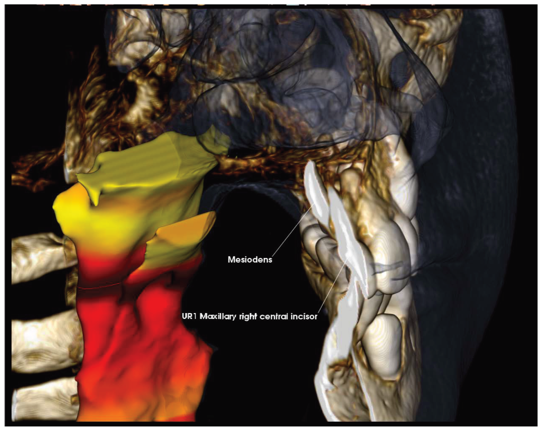
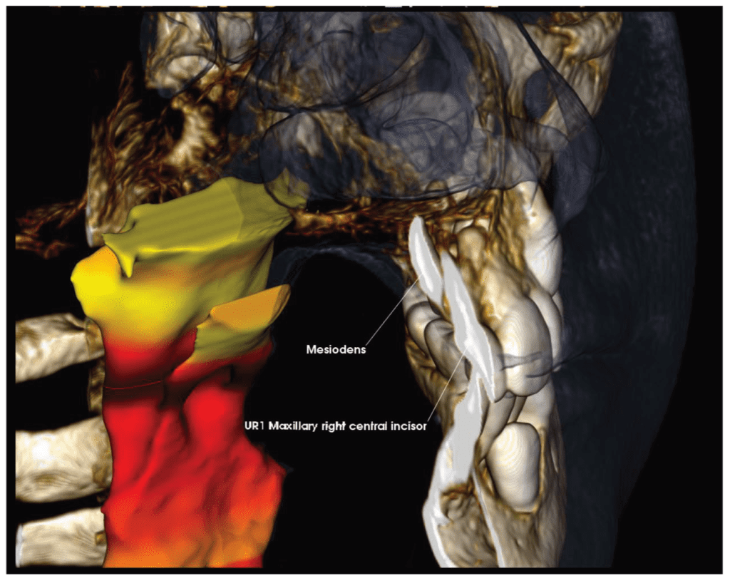
The scan allowed for precise visualization of an inverted and impacted mesiodens located palatal to the central incisors (Figures 4 & 5). CBCTs have the power to reveal even the slightest root resorption caused by an impacted tooth; in this case we can see the mesiodens is in close proximity, but not contact, with the adjacent teeth and no resorption of the permanent teeth is present. The crown of the tooth can be seen interrupting the floor of the nasal cavity.
“Immediate removal of mesiodens is usually indicated in the following situations; inhibition or delay of eruption, displacement of the adjacent tooth, interference with orthodontic appliances, presence of pathologic condition, or spontaneous eruption of the supernumerary tooth.”6 Thus, the ability to visualize the mesiodens in three dimensions (Figure 8) and recognize that it was not immediately affecting the permanent dentition was tremendously advantageous to the evolving treatment plan. Close follow-up without intervention was elected in this situation.
i-CAT FLX 3D imaging technology
Figure 4. Sagittal slice of an i-CAT FLX 13 x 16 cm FOV QuickScan (8.9 seconds) of UR1 (tooth #8) and inverted mesiodens
Figure 5. 3D Rendering of anterior maxilla. Note space between the inverted mesiodens and UR1 (tooth #8)
Phase II
Ideally, Phase II will consist of 6 to 8 months of non-extraction therapy. However, there is a chance that the patient will require extraction of permanent teeth to create additional space. An Oral Surgeon was consulted on the relationship of the mesiodens with the permanent central incisors and it was determined that surgical intervention could be delayed. This allowed the orthodontist to proceed with treatment to determine if orthodontic extractions would also be required, so the patient would only have to undergo one surgical visit. Consolidating the extractions into a single procedure may lead to shorter total recovery time, less need for office visits, and overall lower costs of treatment.
After deciding to delay extraction of the mesiodens, Phase II treatment was initiated and included bracket placement and a Hyrax Upper Rapid Palatal Expander (RPE) to gain more space for the maxillary canines. At the time of writing this clinical case, the patient is still on track for non-extraction therapy. In the upcoming months a final determination will be made as to if orthodontic extractions will be required.
Figure 6. Pre-Phase II Orthodontic Photos taken approximately two (2) years after initial consultation
Testimonial
This case is one of many examples that further supports our decision to add 3D CBCT imaging to our orthodontic practice. Patients greatly benefit from three-dimensional radiographic examinations, with pre-treatment images that are captured in i- CAT’s independently verified low-dose mode5. The i-CAT FLX allows me to visualize all the anatomy of a standard panoramic/cephalometric, with the additional power to uncover true anatomic relationships, including the exact proximity of teeth to each other.
This increased visualization is vital to comprehensive treatment, not just for dental needs, but also for TMJ, airway analysis, and orthognathic and oral surgery planning.
Most importantly, I can capture these views with an effective dose as low 11.4 microsieverts (µSv)5. I find great confidence in the fact that I can offer my patients a more accurate diagnosis and treatment plan at a dose “comparable with conventional panoramic examinations.”5
We are consistently looking for ways to enhance the patient experience and create better and more efficient treatment outcomes. My i-CAT FLX consistently provides me with the insight and confidence to deliver quality care to my patients and their families. Additionally, it is an incredible educational tool, so that my patients better understand and are more invested in their treatment plans.

Figure 7. 3D Rendering with airway visualization, highlighting cropped view of midline with finding of inverted mesiodens distally presenting posterior to maxillary right central incisor
Conclusion
Accurate and precise localization of an inverted mesiodens allowed the orthodontist to delay extraction without impacting the orthodontic treatment; this allowed them to provide a better overall dental experience for the patient. Invasive treatment on a young patient can often be scary to both the patient and their parents; nobody wants their child to have surgery, especially if it could have been avoided. Because dental fear and anxiety acquired in childhood can persist into adulthood, I view these choices as critical in the prevention of negative associations with dental treatment, thereby assisting my patients to be confident in their oral health in the long run.
- https://www.ncbi.nlm.nih.gov/pmc/articles/PMC3467922/
- Mesiodens: a retrospective study of 44 patients. Alaejos C, Contreras MA, Buenechea R, Berini L, Gay C Med Oral. 2000 Mar-Apr; 5(2):81-88.
- https://www.kavo.com/en-us/imaging-solutions/i-cat-flx-v-series-cone-beam-3d-imaging
- Ludlow JB, Walker C. Assessment of phantom dosimetry and image quality of i-CAT FLX cone-beam computed tomography. Am J Orthod Dentofacial Orthop 2013; 144: 802–17. doi: 10.1016/j.ajodo.2013.07.013
- CDC Website; Radiation Safety; https://www.cdc.gov/nceh/radiation/safety.html
- https://www.ncbi.nlm.nih.gov/pmc/articles/PMC3184724/
Case Study published with permission by Kavo Imaging. The opinions and surgical techniques presented herein are those of Greg Greenberg, DDS. Kavo Kerr is a medical device manufacture and does not dispense medical advice. Clinicians should use their own judgment in treating their patients. Greg Greenberg, DDS, is not a paid consultant of KaVo Kerr.
